Getting Started
You can use Kitware’s Computational ModelBuilder to develop ATS analyses and generate ATS input files. CMB modelbuilder is a desktop application for simulation modeling and preprocessing.
1. Download and install CMB modelbuilder
CMB modelbuilder release packages are generated nightly as part of Kitware’s software development process and uploaded to a public collection named ComputationalModelBuilder on https://data.kitware.com. The are a number of different directories underneath that collection. Users should navigate to the CMB-public/Nightly/MasterBranch folder, where packages are uploaded to subdirectories listed by date code (YYYY-MM-DD).
We have extracted three known working versions from those nightlies and we host them here. Select the download matching your system type.
To install, simply download and unzip the file. (There is no setup.exe or other installer for windows, for example.) The macOS dmg file contains two folders; you only need to copy the modelbuilder 6.3.0 folder onto your file system.
2. Setup Modelbuilder Views
When starting modelbuilder for the first time, a number of view panels appear on the left-hand side of the application, as shown in this screenshot.
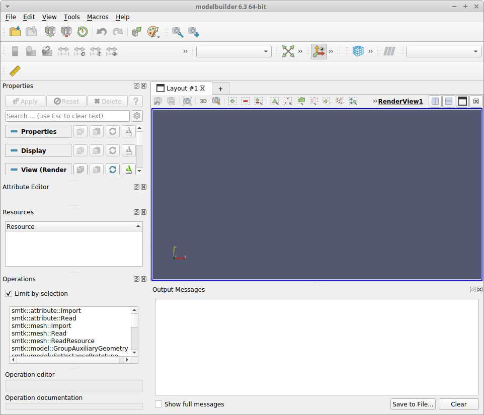
Each panel is a Dock Widget that can be closed or undocked in the same way that ParaView panels work. For simulation preprocessing, the following setup is recommended, although users can chose whatever configuration they prefer:
- Close the Properties and Operations panels
- This should leave 2 view panels, labeled Attribute Editor and Resources.
- Undock the Resources view and drag it over the Attribute Editor view, so that it docks as a second tab.
- Drag the left-hand panel so that it occupies approximately 1/3 of the overall widow size.
- On the right-hand size, drag the Output Messages panel to be smaller, leaving more space for the Render view.
- To free up more vertical space, you can also remove tool bars from the View menu. The above screenshot shows a “Ruler” icon in an otherwise empty toolbar. To hide that, uncheck the “View” => “Toolbars” => “Measurement Tools” item.
The end result should look something like this screenshot.
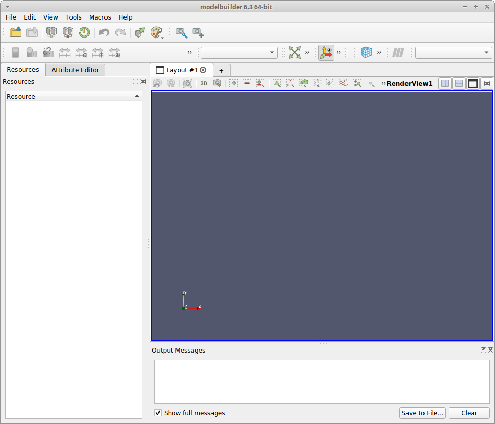 .
.
3. Download ATS workflow files
To use CMB modelbuilder for ATS preprocessing, download and unzip the latest release from the ResonantHPC package. The ats-cmb-v* directory includes a set of “template” files, which specify the various properties used by the simulation code, plus a set of python scripts that are used to generate ATS input files.
4. Create modelbuilder project
Following are the intial steps for creating an ATS input file, using the ats-demos for reference. Specifically this covers the beginning steps to implement the 01_richards_steadystate example.
Load ATS template
The first step for producing any simlation is to load the modelbuilder user interface “template”, which specifies the various properties used by the simulation code. These files use XML format, but typically have the extension .sbt.
Use the “File” => “Open” menu item and select ats.sbt file in the ats-cmb-v* directory previously downloaded. Because this example does not use any geometric model input, you can expand the left hand panel to expose more of the
Attirbute Editor tab. The Attribute Editor should now display these horizontal tabs, corresponding to the top-level sections of the ATS input specification.
- Mesh
- Region
- Coordinator/Time
- Process Kernels
- Visualization
- Checkpoint
- Observation
- State
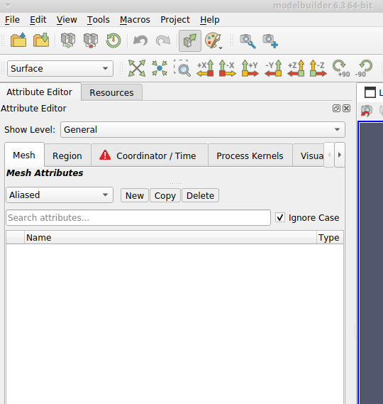
The left-hand side of the user interface should look similar to this screenshot.
Save attribute resource
When modelbuilder first opened the ats.sbt file, it created a CMB attribute resource instance, which stores the data entered from the modelbuilder user interface. As with any work product, it is a good idea to write that resource to the file system as you make changes. To do this, select the “File” => “Save Resource” menu item, which will open a file dialog to select the directory and filename to use. Navigate to some work area you use for data files and enter “demo01.smtk” in the “File name” field. Note that modelbuilder resource files must use the extension “.smtk” (which stands for “Simulation Modeling ToolKit).
Mesh attribute
In the Mesh tab, we want to create one attribute to represent the problem domain. To do that, click on the dropdown box just below the “Mesh Attributes” label and select, select the “Generate Mesh 3D” item, and click the “New” button to the right of the dropdown box. In repsonse, modelbuilder will create and display a new mesh “attribute” as one row in the middle section and with an editing panel below the list area. The left-hand side should now look like this screenshot.
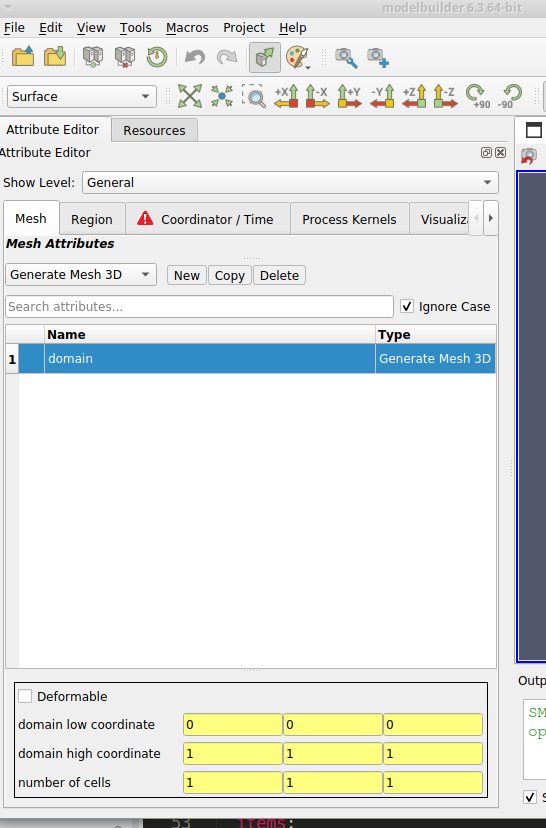
In the middle area, double-click on the Name item (“mesh.generate.3d-0”) to edit the text and change it to “domain” (click <Enter> to finish editing.) Note that all projects must have one mesh named “domain” in order for modelbuilder to generate a working ATS input file.
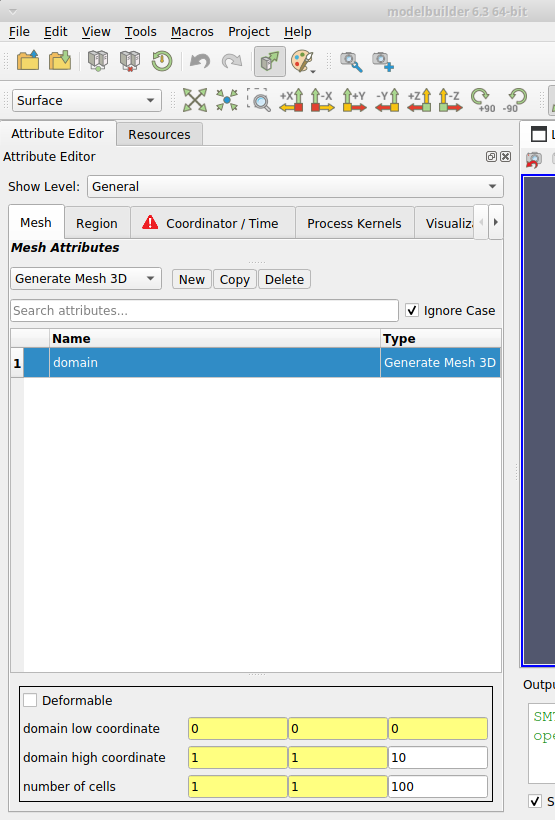
In the lower section are editing panels labeled “domain low coordinate”, “domain high coordinate”, and “number of cells”.
- You can leave the “domain low coordinate” at 0, 0, 0.
- Change the “domain high coordinate” to 1, 1, 10 (which only requires editing the third column).
- Change the “number of cells” to 1, 1, 100 (which only requires editing the third column.)
When complete, the tab should look like this screenshot, with the only difference being the two fields edited in the lower section.
Note that after editing an item, the background color changes from yellow to white. The yellow color indicates that the current value is the default value specified in the .sbt templates. White indicates the value is not the template default.
The background color is red if a value is invalid or missing. The modelbuilder user interface applies some validation checks which prevent users from enterting invalid values. For example, you cannot enter text in the various fields for this (mesh) attribute. You also cannot enter negative values for the “number of cells” fields.
Now would be a good time to save the attribute resource, before going to the next section.
Region attributes
A total of seven region attributes are used in the ATS Demo01 example. To specify these, move to the “Region” tab in the attribute editor.
The first region attribute is type region: box 3D, so select that in the dropdown list and click the “New” button. Edit the name to be “computational domain” and enter the coordinates
- low coordinate 0,0,0
- high coordinate: 1, 1, 10
The other six attributes are of type region: plane 3D. Create
those attributes using the following data.
  name: bottom face
  items:
    - 'point':  [0.5, 0.5,  0.0]
    - 'normal': [0.0, 0.0, -1.0]

  name: east face
  items:
    - 'point':  [1.0, 1.0, 0.0]
    - 'normal': [1.0, 0.0, 0.0]

  name: north face
  items:
    - 'point':  [1.0, 1.0, 0.0]
    - 'normal': [0.0, 1.0, 0.0]

  name: south face
  items:
    - 'point':  [0.0,  0.0, 0.0]
    - 'normal': [0.0, -1.0, 0.0]

  name: surface
  items:
    - 'point':  [0.5, 0.5, 10.0]
    - 'normal': [0.0, 0.0, 1.0]

  name: west face
  items:
    - 'point':  [0.0, 0.0, 0.0]
    - 'normal': [-1.0, 0.0, 0.0]
Once again, you should probably save the attribute resource before continuing.
Other attributes
Continue entering and editig attributes in the remaining tabs to complete an analysis specification.
- Coordinator/Time
- Process Kernels
- Visualization
- State
The ats-examples Demo01 does not use the Checkpoint and Observation sections.
5. Generate ATS input file
Modelbuilder uses python scripts to generate ATS input files from the data stored in the attribute resource. To do this, use the “File” => “Export Simulation…” menu item, which brings up a file dialog. Select the ats.py file from the ResonantHPC package, which then brings up a small dialog with two fields, as shown here:
In the Attributes dropdown, select the “ats” item, which will be the only item in the list (unless you have loaded multiple attribute resources). In the “Output File” item, enter a filename or path to be generated (typically with a .xml extension). When both values are set, the “Apply” button should be enabled; clicking it will write the file. If the process succeeds, the dialog will close.
6. Platform-specific Notes
Linux
The Linux modelbuilder package is built using CentOS 7. On some linux systems, including Ubuntu 16.04, you might see an error message on startup like this:
error while loading shared libraries: libcrypto.so.10: cannot open shared object file: No such file or directory
You can workaround this by deleting or moving files that match libcrypt*, for example
rm -f lib/libcrypt*
These crypto libraries are not needed to run modelbuilder on the desktop (they are for connecting paraview to remote servers).
macOS
Because the app is not signed, macOS might not give you permission to run the app by double-clicking “modelbuilder.app” in Finder. If that occurs, right-click on “modelbuilder.app” and select the “Open” menu item. In response, macOS should display a pop-up window where you can chose to open the application. Once you have done that, you should be able to run by double-clicking “modelbuilder.app”.
On some macOS systems, modelbuilder crashes the first time it is run. The underlying cause is not fully understood but is related to the python libraries internal to modelbuilder. Restarting the application has been successful.
Windows
The first time you run modelbuilder.exe, your system might display a blue popup with the title “Windows protected your PC”. This is because our packages are not signed with Microsoft. You can proceed to run modelbuilder by clicking the “More Info” link, which brings up a “Run anyway” button.